“TF-A overview”的版本间的差异
(创建页面,内容为“== Trusted Firmware-A == File: STM32MPU Embedded Software architecture overview.png|link=STM32MPU Embedded Software architecture overview|thumb|Zoom out to STM32MP…”) |
|||
| 第1行: | 第1行: | ||
== Trusted Firmware-A == | == Trusted Firmware-A == | ||
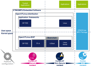
[[File: STM32MPU Embedded Software architecture overview.png|link=STM32MPU Embedded Software architecture overview|thumb|Zoom out to STM32MPU Embedded Software]] | [[File: STM32MPU Embedded Software architecture overview.png|link=STM32MPU Embedded Software architecture overview|thumb|Zoom out to STM32MPU Embedded Software]] | ||
| − | Trusted Firmware- | + | Trusted Firmware-A是Arm提供的安全世界软件的参考实现。<sup>®</sup>. 它最初是为Armv8-A平台设计的,并已由意法半导体(STMicroelectronics)改编为用于Armv7-A平台。 Arm正在转让Trusted Firmware项目,该项目将由Linaro作为开源项目进行管理。<ref>https://www.trustedfirmware.org/</ref> |
| − | + | 当使用STM32 MPU平台时,它用作STM32 MPU平台上的第一阶段引导加载程序(FSBL)。 [[Boot_chains_overview#STM32MP boot chains|trusted boot chain]]. | |
| − | + | 该代码在BSD-3-Clause许可下是开源的,可以在github上找到 | |
| − | <ref>https://github.com/ARM-software/arm-trusted-firmware</ref>, | + | <ref>https://github.com/ARM-software/arm-trusted-firmware</ref>, 包括有关Trusted Firmware-A安装的最新文档 <ref name=readme>{{CodeSource | TF-A | readme.rst}}</ref>. |
| − | Trusted Firmware- | + | Trusted Firmware-A还使用各种Arm接口标准实施安全的监视器: |
| − | * | + | * 电源状态协调接口(PSCI) <ref name=psci>http://infocenter.arm.com/help/topic/com.arm.doc.den0022d/Power_State_Coordination_Interface_PDD_v1_1_DEN0022D.pdf</ref> |
| − | * | + | * 可信板启动要求(TBBR)<ref>Arm DEN0006C-1</ref> |
| − | * | + | * SMC呼叫约定 <ref name=smc>http://infocenter.arm.com/help/topic/com.arm.doc.den0028b/ARM_DEN0028B_SMC_Calling_Convention.pdf </ref> |
| − | * | + | * 系统控制和管理界面<ref>http://infocenter.arm.com/help/topic/com.arm.doc.den0056a/DEN0056A_System_Control_and_Management_Interface.pdf </ref> |
| − | Trusted Firmware-A | + | Trusted Firmware-A 通常缩写为 TF-A. |
== Architecture == | == Architecture == | ||
2020年11月2日 (一) 10:06的版本
Trusted Firmware-A
Trusted Firmware-A是Arm提供的安全世界软件的参考实现。®. 它最初是为Armv8-A平台设计的,并已由意法半导体(STMicroelectronics)改编为用于Armv7-A平台。 Arm正在转让Trusted Firmware项目,该项目将由Linaro作为开源项目进行管理。[1]
当使用STM32 MPU平台时,它用作STM32 MPU平台上的第一阶段引导加载程序(FSBL)。 trusted boot chain.
该代码在BSD-3-Clause许可下是开源的,可以在github上找到 [2], 包括有关Trusted Firmware-A安装的最新文档 [3].
Trusted Firmware-A还使用各种Arm接口标准实施安全的监视器:
Trusted Firmware-A 通常缩写为 TF-A.
Architecture
The global architecture of TF-A is explained in the Trusted Firmware-A design [8] document.
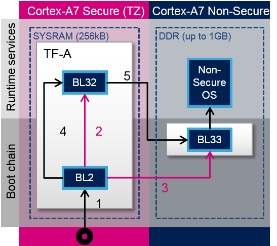
TF-A is divided into several binaries, each with a dedicated main role. For 32-bit Arm processors (AArch32), it is divided into four steps (in order of execution):
- Boot loader stage 1 (BL1) application processor trusted ROM
- Boot loader stage 2 (BL2) trusted boot firmware
- Boot loader stage 3-2 (BL32) runtime software
- Boot loader stage 3-3 (BL33) non-trusted firmware
BL1, BL2 and BL32 are parts of TF-A.
BL1 is now optional, and can be removed by enabling the compilation flag: BL2_AT_EL3. It is then removed for the STM32MP1, as all BL1 tasks are done by ROM code, or BL2.
BL33 is outside of TF-A. This is the first non-secure code loaded by TF-A. During the boot sequence, this is the secondary stage boot loader (SSBL). For STM32 MPU platforms, the SSBL is U-Boot by default.
TF-A can manage its configuration with a device tree, as this is the case on STM32MP1. It is a reduced version of the Linux kernel one, with only the devices used during boot. It can be configured with STM32CubeMX.
In STMicroelectronics' implementation, the 2 binaries, BL2 and BL32, and the device tree are put together in a single binary, to be loaded at once to the SYSRAM by the ROM code.

TF-A loading steps:
- ROM code loads TF-A binary and calls BL2
- BL2 prepares BL32
- BL2 loads BL33
- BL2 calls BL32
- BL32 calls BL33
Boot loader stages
BL1
BL1 is the first stage executed, and is designed to act as ROM code; it is loaded and executed in internal RAM. It is not used for the STM32MP1. As the STM32MP1 has its own proprietary ROM code, this part can be removed and BL2 is then the first TF-A binary to be executed.
BL2
BL2 (trusted boot firmware) is in charge of loading the next-stage images (secure and non secure). To achieve this role, BL2 has to initialize all the required peripherals.
It has to initialize the security components.
For the STM32MP15, these security peripherals are:
- boot and security, and OTP control (BSEC internal peripheral)
- extended TrustZone protection controller (ETZPC internal peripheral)
- TrustZone address space controller for DDR (TZC internal peripheral)
BL2 is also in charge of initializing the DDR and clock tree.
The boot peripheral has to be initialized.
On the STM32MP15, it can be one of the following:
- SD-card via the SDMMC internal peripheral
- eMMC via the SDMMC internal peripheral
- NAND via the FMC internal peripheral
- NOR via the QUADSPI internal peripheral
USB (OTG internal peripheral) or UART(USART internal peripheral) are used when Flashing, see STM32CubeProgrammer for more details.
BL2 also integrates image verification and authentication. Authentication is achieved by calling BootROM verification services.
At the end of its execution, after having loaded BL32 and the next boot stage (BL33), BL2 jumps to BL32.
BL32
BL32 provides runtime secure services. In TF-A, the BL32 default implementation is SP_min solution. It is described in the TF-A functionality list [3] as: "A minimal AArch32 Secure Payload (SP_MIN) to demonstrate PSCI [4] library integration with AArch32 EL3 Runtime Software."
This minimal implementation can be replaced with a trusted OS or trusted environment execution (TEE), such as OP-TEE. Both solutions (SP_min or OP-TEE) are supported by STMicroelectronics for STM32MP1.
BL32 acts as a secure monitor and thus provides secure services to non-secure OSs. These services are called by non-secure software with secure monitor calls [6].
This code is in charge of standard service calls, like PSCI [4].
It also provides STMicroelectronics dedicated services, to access secure peripherals. On the STM32MP1, these services are used to access RCC internal peripheral, PWR internal peripheral, RTC internal peripheral or BSEC internal peripheral.
References
- ↑ https://www.trustedfirmware.org/
- ↑ https://github.com/ARM-software/arm-trusted-firmware
- ↑ 3.03.1 readme.rst| |}} readme.rst
- ↑ 4.04.14.2 http://infocenter.arm.com/help/topic/com.arm.doc.den0022d/Power_State_Coordination_Interface_PDD_v1_1_DEN0022D.pdf
- ↑ Arm DEN0006C-1
- ↑ 6.06.1 http://infocenter.arm.com/help/topic/com.arm.doc.den0028b/ARM_DEN0028B_SMC_Calling_Convention.pdf
- ↑ http://infocenter.arm.com/help/topic/com.arm.doc.den0056a/DEN0056A_System_Control_and_Management_Interface.pdf
- ↑ docs/firmware-design.rst| |}} docs/firmware-design.rst
<securetransclude src="ProtectedTemplate:PublicationRequestId" params="9178 | 2018-10-24 | PhilipS"></securetransclude>
