MB1272
来自百问网嵌入式Linux wiki
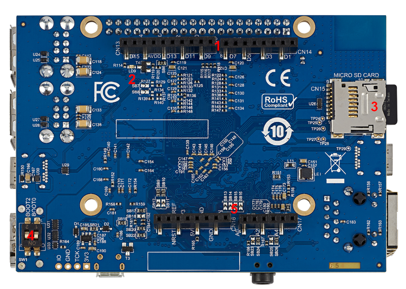
MB1272 board overview.
Board overview
MB1272 motherboard STM32MP157x 12x12 with PMIC and DDR3, revision C-0.1: part of the S{{#vardefine:info|}}{{#vardefine:typ|}}{{#vardefine:typ| Discovery kit}}{{#vardefine:info|![]() }}STM32MP157x-DKx{{#var:typ}} {{#var:info}}.
}}STM32MP157x-DKx{{#var:typ}} {{#var:info}}.
Note that:
- MB1272 for the {{#vardefine:info|}}{{#vardefine:typ|}}{{#vardefine:info|
 }}STM32MP157A-DK1{{#var:typ}} {{#var:info}} and {{#vardefine:info|}}{{#vardefine:typ|}}{{#vardefine:info|
 }}STM32MP157D-DK1{{#var:typ}} {{#var:info}} Discovery kits doesn't include the "WLAN + Bluetooth" component (muRata LBEE5KL1DX)
 - MB1272 for {{#vardefine:info|}}{{#vardefine:typ|}}{{#vardefine:info|}}STM32MP157C-DK2{{#var:typ}} {{#var:info}} and {{#vardefine:info|}}{{#vardefine:typ|}}{{#vardefine:info|}}STM32MP157F-DK2{{#var:typ}} {{#var:info}} Discovery kits includes the "WLAN + Bluetooth" component (Murata LBEE5KL1DX)

<securetransclude src="ProtectedTemplate:InternalInfo" params="CN3 could be used to connect a CR2032 lithium battery, wired on a Molex Picoblade 2 circuits pitch 1.25mm type 51021-0200 (1-VBAT, 2-GND).<br/>Like Thinkpad 02K6541, 02K6572, 02K7075, 02K7087, 08K8050, 92P0986, 92P0991 models."></securetransclude>
Details of some LEDs:
- LD1: red if USB type A connection established
- LD2: green if power connection established
- LD3: green flashing the Ethernet connection established
- LD4: red flashing if ST-LINK/V2-1 connection not established, else green
- LD5, LD6, LD7, LD8: some user LEDs are used to reflect the system activity, whereas the others are left free and can be directly used by the application, as explained in the LEDs and buttons on STM32 MPU boards article