Soundcard configuration
目录
Overview
本文介绍了如何在将ST音频外围设备以及分配给Linux® OS的外部音频组件以及 STM32MP1 boards 时进行配置。 在这种情况下,它们由ALSA框架控制。
在ALSA framework的ASoC层中,音频硬件组件被描述为CPU DAIs and codec,它们链接在一起以创建DAI链接。声卡是收集一组DAI链接的软件组件。 以下STM32 MPU板的每个部分都描述了一个或多个声卡。 提供了每个声卡的示意图,以及其静态和动态配置的方式。
Sound card schematic
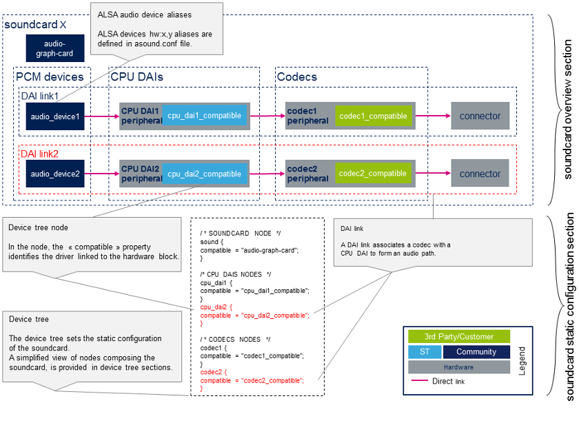
声卡原理图概述了构成声卡的硬件和软件组件及其关系。
下面给出的示例声卡示意图强调了声卡和设备树部分之间的链接。

Static configuration
- Device tree
设备树允许描述,配置和连接音频硬件组件以定义声卡。用户必须遵循音频图形卡绑定[1] 来配置声卡和设备图绑定[2] 来连接音频组件。 用户还必须参考音频组件(编解码器和CPU DAI)绑定,以正确配置这些组件。 音频组件的绑定可以在以下各节的设备树样本中以及References chapter中找到。
STMicroelectronics组态工具 STM32CubeMX, 允许生成CPU DAI设备树节点。
| STM32CubeMX不允许配置声卡和编解码器节点,这取决于板。声卡节点和编解码器节点必须通过用户部分手动填充。 |
- asound.conf [3]
可选的asound.conf[3] 系统全局自定义设置文件提供了额外的功能,例如路由和音频样本转换。可以在/ etc目录中找到它。
- 声卡配置文件[3]
alsa-lib层在 /usr/share/alsa/cards 目录中提供卡配置文件。 这些文件允许在标准设备(例如"front", "hdmi" 或 "iec958"设备)上映射ALSA硬件设备。声卡设备树节点中定义的标签定义了卡的名称。 根据 /usr/share/alsa/cards/aliases.conf 映射,从此卡名称中检索卡配置。
STM32MP15 evaluation board sound card configuration
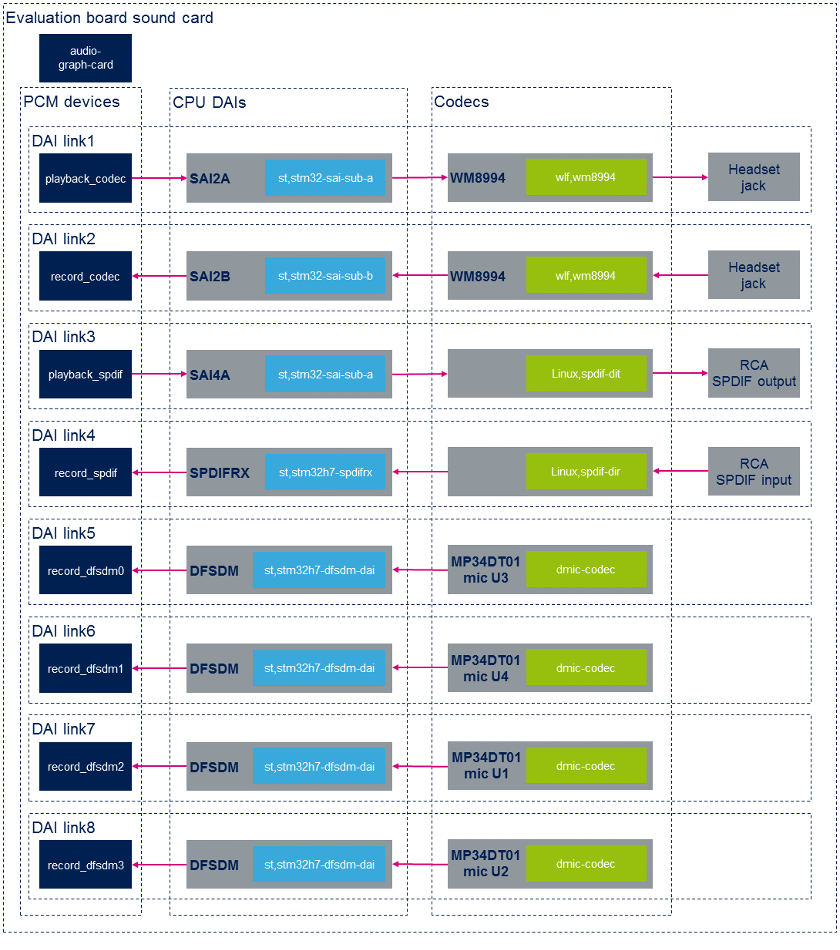
Sound card overview

Static configuration
以下摘录来自STM32MP15评估板设备树。这里仅显示与声卡关联的节点以及最相关的属性。例如,使用green字体强调链接节点以形成第一个DAI链接的属性。
/ * SOUNDCARD */
	sound {
		compatible = "audio-graph-card[1]";
		label = "STM32MP1-EV";			/* Sound card identified as STM32MP1EV in ALSA */
		routing =
			"AIF1CLK" , "MCLK1",
			"AIF2CLK" , "MCLK1",
			"IN1LN" , "MICBIAS2",
			"DMIC2DAT" , "MICBIAS1",
			"DMIC1DAT" , "MICBIAS1";
		dais = <&sai2a_port &sai2b_port &sai4a_port &spdifrx_port
			&dfsdm0_port &dfsdm1_port &dfsdm2_port &dfsdm3_port>;
	};

/ * CODECS */
	spdif_out: spdif-out {
		compatible = "linux,spdif-dit[4]";

		spdif_out_port: port@0 {
			spdif_out_endpoint: endpoint {
				remote-endpoint = <&sai4a_endpoint>;
			};
		};
	};

	spdif_in: spdif-in {
		compatible = "linux,spdif-dir[5]";
		spdif_in_port: port@0 {
			spdif_in_endpoint: endpoint {
				remote-endpoint = <&spdifrx_endpoint>;
			};
		};
	};

	dmic0: dmic@0 {
		compatible = "dmic-codec";
		port {
			dmic0_endpoint: endpoint {
				remote-endpoint = <&dfsdm_endpoint0>;
			};
		};
	};

	dmic1: dmic@1 {
		compatible = "dmic-codec";
		port {
			dmic1_endpoint: endpoint {
				remote-endpoint = <&dfsdm_endpoint1>;
			};
		};
	};

	dmic2: dmic@2 {
		compatible = "dmic-codec";
		port {
			dmic2_endpoint: endpoint {
				remote-endpoint = <&dfsdm_endpoint2>;
			};
		};
	};

	dmic3: dmic@3 {
		compatible = "dmic-codec";
		port {
			dmic3_endpoint: endpoint {
				remote-endpoint = <&dfsdm_endpoint3>;
			};
		};
	};
};

&i2c2 {
	wm8994: wm8994@1b {
		compatible = "wlf,wm8994";
		...
		clocks = <&sai2a>;
		clock-names = "MCLK1";

		ports {
			#address-cells = <1>;
			#size-cells = <0>;

			wm8994_tx_port: port@0 {
				wm8994_tx_endpoint: endpoint {
					remote-endpoint = <&sai2a_endpoint>;
				};
			};

			wm8994_rx_port: port@1 {
				wm8994_rx_endpoint: endpoint {
					remote-endpoint = <&sai2b_endpoint>;
				};
			};
		};
	};
};

/* CPU DAIS */
&sai2 {
	clocks = <&rcc SAI2>, <&rcc PLL3_Q>, <&rcc PLL4_Q>;
	pinctrl-names = "default", "sleep";
	pinctrl-0 = <&sai2a_pins_a>, <&sai2b_pins_a>;
	pinctrl-1 = <&sai2a_sleep_pins_a>, <&sai2b_sleep_pins_a>;
	clock-names = "pclk", "x8k", "x11k";

	sai2a: audio-controller@4400b004 {
		compatible = "st,stm32-sai-sub-a";
		dma-names = "tx";				/* SAI set as transmitter */
		clocks = <&rcc SAI2_K>;
		clock-names = "sai_ck";

		sai2a_port: port@0 {
			sai2a_endpoint: endpoint {
				remote-endpoint = <&wm8994_tx_endpoint>;
				format = "i2s";
				mclk-fs = <256>;		/* SAI is master clock provider */
			};
		};
	};

	sai2b: audio-controller@4400b024 {
		compatible = "st,stm32-sai-sub-b";
		dma-names = "rx";				/* SAI set as receiver */
		clocks = <&rcc SAI2_K>, <&sai2a>;
		clock-names = "sai_ck", "MCLK";

		sai2b_port: port@0 {
			sai2b_endpoint: endpoint {
				remote-endpoint = <&wm8994_rx_endpoint>;
				format = "i2s";
				mclk-fs = <256>;		/* SAI is master clock provider */
			};
		};
	};
};

&sai4 {
	clocks = <&rcc SAI4>, <&rcc PLL3_Q>, <&rcc PLL4_Q>;
	clock-names = "pclk", "x8k", "x11k";

	sai4a: audio-controller@50027004 {
		compatible = "st,stm32-sai-sub-a";
		dma-names = "tx";
		st,iec60958;					/* SAI configured for S/PDIF protocol*/
		pinctrl-names = "default", "sleep";
		pinctrl-0 = <&sai4a_pins_a>;
		pinctrl-1 = <&sai4a_sleep_pins_a>;
 		clocks = <&rcc SAI4_K>;
		clock-names = "sai_ck";

		sai4a_port: port@0 {
			sai4a_endpoint: endpoint {
				remote-endpoint = <&spdif_out_endpoint>;
			};
		};
	};
};

&spdifrx {
 	compatible = "st,stm32h7-spdifrx";
 	pinctrl-names = "default", "sleep";
	pinctrl-0 = <&spdifrx_pins_a>;
	pinctrl-1 = <&spdifrx_sleep_pins_a>;

	spdifrx_port: port@0 {
		spdifrx_endpoint: endpoint {
			remote-endpoint = <&spdif_in_endpoint>;
		};
	};

&dfsdm {
	compatible = "st,stm32mp1-dfsdm";
	pinctrl-names = "default", "sleep";
	pinctrl-0 = <&dfsdm_clkout_pins_a
		     &dfsdm_data1_pins_a &dfsdm_data3_pins_a>;
	pinctrl-1 = <&dfsdm_clkout_sleep_pins_a
		     &dfsdm_data1_sleep_pins_a &dfsdm_data3_sleep_pins_a>;
	spi-max-frequency = <2048000>;

	clocks = <&rcc DFSDM_K>, <&rcc ADFSDM_K>;
	clock-names = "dfsdm", "audio";

	dfsdm0: filter@0 {
		compatible = "st,stm32-dfsdm-dmic";
		st,adc-channels = <3>; 	 	 	/* Use channel 3, shared with mic U3 */
		st,adc-channel-names = "dmic_u1"; 	/* Left mic U1 associated with Right mic U3, for stereo */
		st,adc-channel-types = "SPI_R"; 	/* Rising edge for left channel */
		st,adc-channel-clk-src = "CLKOUT"; 	/* CKOUT clocks the microphones */
		st,filter-order = <3>;

		asoc_pdm0: dfsdm-dai {
			compatible = "st,stm32h7-dfsdm-dai";
			#sound-dai-cells = <0>;
			io-channels = <&dfsdm0 0>;
			cpu_port0: port {
				dfsdm_endpoint0: endpoint {
					remote-endpoint = <&dmic0_endpoint>;
				};
			};
		};
	};

	dfsdm1: filter@1 {
		compatible = "st,stm32-dfsdm-dmic";
		st,adc-channels = <1>;
		st,adc-channel-names = "dmic_u2";
		st,adc-channel-types = "SPI_F";
		st,adc-channel-clk-src = "CLKOUT";
		st,filter-order = <3>;

		asoc_pdm1: dfsdm-dai {
			compatible = "st,stm32h7-dfsdm-dai";
			#sound-dai-cells = <0>;
			io-channels = <&dfsdm1 0>;
			cpu_port1: port {
				dfsdm_endpoint1: endpoint {
					remote-endpoint = <&dmic1_endpoint>;
				};
			};
		};
	};

	dfsdm2: filter@2 {
		compatible = "st,stm32-dfsdm-dmic";
		st,adc-channels = <3>; 	 	 	/* Use channel 3, shared with mic U1 */
		st,adc-channel-names = "dmic_u3"; 	/* Right mic U3 associated with Left mic U1, for stereo */
		st,adc-channel-types = "SPI_F"; 	/* Falling edge for Right channel */
		st,adc-channel-clk-src = "CLKOUT";
		st,filter-order = <3>;

		asoc_pdm2: dfsdm-dai {
			compatible = "st,stm32h7-dfsdm-dai";
			#sound-dai-cells = <0>;
			io-channels = <&dfsdm2 0>;
			cpu_port2: port {
				dfsdm_endpoint2: endpoint {
					remote-endpoint = <&dmic2_endpoint>;
				};
			};
		};
	};

	dfsdm3: filter@3 {
		compatible = "st,stm32-dfsdm-dmic";
		st,adc-channels = <1>;
		st,adc-channel-names = "dmic_u4";
		st,adc-channel-types = "SPI_R";
		st,adc-channel-clk-src = "CLKOUT";
		st,filter-order = <3>;

		asoc_pdm3: dfsdm-dai {
			compatible = "st,stm32h7-dfsdm-dai";
			#sound-dai-cells = <0>;
			io-channels = <&dfsdm3 0>;
			cpu_port3: port {
				dfsdm_endpoint3: endpoint {
					remote-endpoint = <&dmic3_endpoint>;
				};
			};
		};
	};
};
用于STMP32MP15评估板的特定于卡的alsa-lib配置文件为/usr/share/alsa/cards/STM32MP1EV.conf。
Dynamic configuration
The table below gives an overview of the controls allowing configuration of the STM32MPU evaluation board "sound" sound card.
| audio device | CPU DAI | codec |
|---|---|---|
| playback_codec | no controls available | configure codec output path |
| record_codec | no controls available | configure codec input path |
| playback_spdif | configure iec958 | no controls available |
| record_spdif | configure SPDFIRX input path | no controls available |
Wolfson wm8994 output configuration
- Control commands to configure aif1 interface to headset output (HPOUT1L/R) path, on wm8994 codec:
amixer -c STM32MP1EV cset name='AIF1DAC1 Volume' '96' '96'
amixer -c STM32MP1EV cset name='Headphone Volume' '63' '63'
amixer -c STM32MP1EV cset name='DAC1 Volume' '50' '50'
amixer -c STM32MP1EV cset name='DAC1L Mixer AIF1.1 Switch' 'on'
amixer -c STM32MP1EV cset name='DAC1R Mixer AIF1.1 Switch' 'on'
amixer -c STM32MP1EV cset name='DAC1 Switch' 'on' 'on'
amixer -c STM32MP1EV cset name='Left Output Mixer DAC Switch' 'on'
amixer -c STM32MP1EV cset name='Right Output Mixer DAC Switch' 'on'
amixer -c STM32MP1EV cset name='Headphone Switch' 'on' 'on'
- Control commands to configure aif1 interface to speaker output (SPKOUTL/RP) path, on wm8994 codec:
amixer -c STM32MP1EV cset name='AIF1DAC1 Volume' '96' '96'
amixer -c STM32MP1EV cset name='DAC1L Mixer AIF1.1 Switch' 'on'
amixer -c STM32MP1EV cset name='DAC1R Mixer AIF1.1 Switch' 'on'
amixer -c STM32MP1EV cset name='DAC1 Switch' 'on','on'
amixer -c STM32MP1EV cset name='DAC1 Volume' '96','96'
amixer -c STM32MP1EV cset name='SPKL DAC1 Volume' '50' '50'
amixer -c STM32MP1EV cset name='SPKR DAC1 Volume' '50' '50'
amixer -c STM32MP1EV cset name='SPKL DAC1 Switch' 'on'
amixer -c STM32MP1EV cset name='SPKR DAC1 Switch' 'on'
amixer -c STM32MP1EV cset name='SPKL Output Switch' 'on'
amixer -c STM32MP1EV cset name='SPKR Output Switch' 'on'
amixer -c STM32MP1EV cset name='Speaker Mode' 'Class AB'
amixer -c STM32MP1EV cset name='Speaker Volume' '50' '50'
amixer -c STM32MP1EV cset name='Speaker Mixer Volume' 3
amixer -c STM32MP1EV cset name='Speaker Reference' 0
amixer -c STM32MP1EV cset name='Speaker Switch' 'on'
Wolfson wm8994 input configuration
- Control commands to configure headset microphone input (IN1LN) to aif2 interface, on wm8994 codec:
amixer -c STM32MP1EV cset name='IN1L PGA IN1LN Switch' 'on'
amixer -c STM32MP1EV cset name='IN1L PGA IN1LP Switch' 'off'
amixer -c STM32MP1EV cset name='IN1L Volume' '25'
amixer -c STM32MP1EV cset name='IN1L Switch' 'on'
amixer -c STM32MP1EV cset name='MIXINL IN1L Switch' 'on'
amixer -c STM32MP1EV cset name='MIXINL IN1L Volume' '1'
amixer -c STM32MP1EV cset name='MIXINL IN1LP Volume' '0'
amixer -c STM32MP1EV cset name='AIF1ADCL Source' 'Left'
amixer -c STM32MP1EV cset name='ADCL Mux' 'ADC'
amixer -c STM32MP1EV cset name='DAC2 Left Sidetone Volume' '12'
amixer -c STM32MP1EV cset name='DAC2 Right Sidetone Volume' '12'
amixer -c STM32MP1EV cset name='AIF2DAC2L Mixer Left Sidetone Switch' 'on'
amixer -c STM32MP1EV cset name='AIF2DAC2R Mixer Right Sidetone Switch' 'on'
amixer -c STM32MP1EV cset name='DAC2 Volume' '96' '96'
amixer -c STM32MP1EV cset name='DAC2 Switch' 'on' 'on'
amixer -c STM32MP1EV cset name='AIF2ADC Volume' '96' '96'
amixer -c STM32MP1EV cset name='AIF2ADC Mux' 'AIF2ADCDAT'
amixer -c STM32MP1EV cset name='AIF2 Boost Volume' '1'
amixer -c STM32MP1EV cset name='ADC OSR' 'Low Power'
SPDFIRX input configuration
- Control commands to configure rx1 input path on SPDFIRX:
amixer -c STM32MP1EV cset name='SPDIFRX input' 1
STM32MP15 disco board sound card configuration
Sound card overview

Static configuration
The extract below is from the STM32MP15 disco board device tree. Only the nodes associated to the sound card, and the most relevant properties are shown here. As an example, the properties linking nodes to form the first DAI link are emphasized with green font.
/ {
/ * SOUNDCARD */
sound {
compatible = "audio-graph-card";
label = "STM32MP1-DK"; /* Sound card identified as STM32MP1DK in ALSA */
routing =
"Playback" , "MCLK",
"Capture" , "MCLK",
"MICL" , "Mic Bias";
dais = <&sai2a_port &sai2b_port &i2s2_port>;
status = "okay";
};
};
/ * CODECS */
&i2c1 {
cs42l51: cs42l51@4a {
compatible = "cirrus,cs42l51";
...
clocks = <&sai2a>;
clock-names = "MCLK";
cs42l51_port: port {
#address-cells = <1>;
#size-cells = <0>;
cs42l51_tx_endpoint: endpoint@0 {
reg = <0>;
remote-endpoint = <&sai2a_endpoint;
frame-master; /* codec is master */
bitclock-master;
};
cs42l51_rx_endpoint: endpoint@1 {
reg = <1>;
remote-endpoint = <&sai2b_endpoint>;
frame-master; /* codec is master */
bitclock-master;
};
};
};
hdmi-transmitter@39 {
compatible = "sil,sii9022";
...
ports {
#address-cells = <1>;
#size-cells = <0>;
port@0 {
reg = <0>;
sii9022_in: endpoint {
remote-endpoint = <<dc_ep0_out>;
};
};
port@1 {
reg = <1>;
sii9022_tx_endpoint: endpoint {
remote-endpoint = <&i2s2_endpoint>;
};
};
};
};
};
/* CPU DAIS */
&sai2 {
clocks = <&rcc SAI2>, <&rcc PLL3_Q>, <&rcc PLL3_Q>;
clock-names = "pclk", "x8k", "x11k";
pinctrl-names = "default", "sleep";
pinctrl-0 = <&sai2a_pins_a>, <&sai2b_pins_b>;
pinctrl-1 = <&sai2a_sleep_pins_a>, <&sai2b_sleep_pins_b>;
status = "okay";
sai2a: audio-controller@4400b004 {
compatible = "st,stm32-sai-sub-a";
#clock-cells = <0>;
dma-names = "tx"; /* SAI set as transmitter */
clocks = <&rcc SAI2_K>;
clock-names = "sai_ck";
sai2a_port: port {
sai2a_endpoint: endpoint {
remote-endpoint = <&cs42l51_tx_endpoint>;
format = "i2s";
mclk-fs = <256>;
dai-tdm-slot-num = <2>;
dai-tdm-slot-width = <32>;
};
};
};
sai2b: audio-controller@4400b024 {
dma-names = "rx"; /* SAI set as receiver */
st,sync = <&sai2a 2>; /* SAI2B is slave of SAI2A */
clocks = <&rcc SAI2_K>, <&sai2a>;
clock-names = "sai_ck", "MCLK";
sai2b_port: port {
sai2b_endpoint: endpoint {
remote-endpoint = <&cs42l51_rx_endpoint>;
format = "i2s";
mclk-fs = <256>;
dai-tdm-slot-num = <2>;
dai-tdm-slot-width = <32>;
};
};
};
};
&i2s2 {
clocks = <&rcc SPI2>, <&rcc SPI2_K>, <&rcc PLL3_Q>, <&rcc PLL4_Q>;
clock-names = "pclk", "i2sclk", "x8k", "x11k";
pinctrl-names = "default", "sleep";
pinctrl-0 = <&i2s2_pins_a>;
pinctrl-1 = <&i2s2_pins_sleep_a>;
status = "okay";
i2s2_port: port {
i2s2_endpoint: endpoint {
remote-endpoint = <&sii9022_tx_endpoint>;
format = "i2s";
mclk-fs = <256>;
};
};
};
The card-specific alsa-lib configuration file for STMP32MP15 Disco board is /usr/share/alsa/cards/STM32MP1DK.conf.
Dynamic configuration
The table below gives an overview of the controls allowing the configuration of the STM32MPU disco board sound card.
| audio device | CPU DAI | codec |
|---|---|---|
| playback_codec | no controls available | configure codec output path |
| record_codec | no controls available | configure codec input path |
| playback_hdmi | no controls available | no controls available |
Cirrus cs42l51 output configuration
- Control commands to configure the aif interface to headset output (AOUTA/B) path, on the cs42l51 codec:
amixer -c STM32MP1DK cset name='PCM Playback Switch' 'on','on'
amixer -c STM32MP1DK cset name='PCM Playback Volume' '63','63'
amixer -c STM32MP1DK cset name='Analog Playback Volume' '204','204'
amixer -c STM32MP1DK cset name='PCM channel mixer' 'L R'
Cirrus cs42l51 input configuration
- Control commands to configure headset microphone input (MICIN1/AIN3A) to the aif interface, on the cs42l51 codec:
amixer -c STM32MP1DK cset name='PGA-ADC Mux Left' '3'
amixer -c STM32MP1DK cset name='Mic Boost Volume' '1','1'
References
- ↑ 1.01.1 Documentation/devicetree/bindings/sound/audio-graph-card.txt| |}} Documentation/devicetree/bindings/sound/audio-graph-card.txt
- ↑ Documentation/devicetree/bindings/graph.txt| |}} Documentation/devicetree/bindings/graph.txt
- ↑ 3.03.13.2 asound.conf
- ↑ Documentation/devicetree/bindings/sound/spdif-transmitter.txt| |}} Documentation/devicetree/bindings/sound/spdif-transmitter.txt
- ↑ Documentation/devicetree/bindings/sound/spdif-receiver.txt| |}} Documentation/devicetree/bindings/sound/spdif-receiver.txt