“I2C device tree configuration”的版本间的差异
| 第71行: | 第71行: | ||
==== I²C internal peripheral related properties ==== | ==== I²C internal peripheral related properties ==== | ||
| − | + | 与I2C内部外围设备和I2C节点所属的I²C总线相关的设备树属性 | |
| − | * '''{{highlight|pinctrl-0&1}}''' | + | * '''{{highlight|pinctrl-0&1}}''' 配置取决于硬件板配置以及I2C设备如何连接到SCL,SDA(如果设备符合SMBus标准,则连接到SMBA)引脚。<br/> 有关引脚配置的更多详细信息,请参见: [[Pinctrl device tree configuration]] |
| − | * '''{{highlight|clock-frequency}}''' | + | * '''{{highlight|clock-frequency}}'''代表I2C总线速度:'''正常(100KHz)''','''快速(400KHz)'''和'''快速+(最高 1MHz)'''。该值以Hz为单位。 |
| − | * '''{{highlight|dmas}}''' | + | * '''{{highlight|dmas}}''' 默认情况下,所有I2C实例均启用DMA。如果不需要,则由用户决定是否“删除”。 |
| − | * '''{{highlight|i2c-scl-rising/falling-time-ns}}''' | + | ''{{highlight|/delete-property/}}'' 用于删除I2C的DMA使用情况。要删除DMA,必须同时插入'''{{highlight|/delete-property/dma-names}}''' 和 '''{{highlight|/delete-property/dmas}}'''。 |
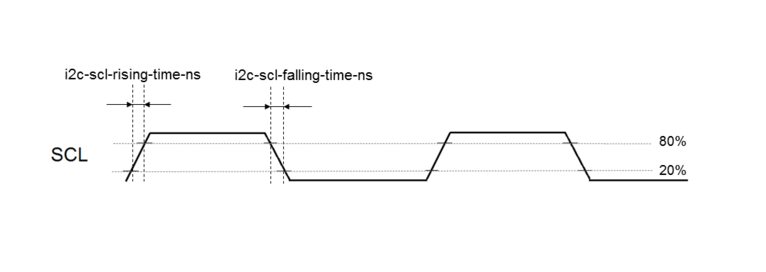
| − | {{Info| | + | * '''{{highlight|i2c-scl-rising/falling-time-ns}}'''是可选值,具体取决于板的硬件特性: 导线长度,电阻和电容的硬件设计。<br/> 这些值必须以纳秒为单位提供,并且可以通过观察示波器上的SCL上升和下降斜率来测量。请参见[[I2C device tree configuration#How to measure I2C timings | how to measure I2C timings]].<br/>I2C驱动程序使用此信息根据请求的 ''{{highlight|clock-frequency}}''来计算准确的I2C时序。 <br/>STM32CubeMX实现了遵循I2C标准并考虑用户输入的算法。 <br/>如果未提供这些值,则驱动程序将使用其默认值。 <br/>提供错误的参数将产生不正确的 ''{{highlight|clock-frequency}}''. 如果驱动程序未能根据用户输入计算时序参数(SCL上升/下降和时钟频率),则时钟频率将降级为较低的频率。'''示例''':如果用户将400 kHz指定为时钟频率,但是算法无法为指定的SCL上升和下降时间生成时序,则时钟频率将降至100 kHz。 |
| + | {{Info| 对于高于100KHz的I2C总线频率,强烈建议使用I2C时序。}} | ||
'''For {{EcosystemRelease | revision=1.2.0 | range=and after}}''' | '''For {{EcosystemRelease | revision=1.2.0 | range=and after}}''' | ||
2020年11月8日 (日) 14:25的版本
目录
Article purpose
本文介绍了如何配置“ I2C内部外围设备”[1] when the peripheral is assigned to Linux® OS,尤其是:
- 如何配置STM32 I2C外设
- 如何配置板上或硬件扩展上存在的STM32外部I2C器件。
使用设备树机制执行配置[2].
它由“STM32 I2C Linux®驱动程序”使用,该驱动程序在 I2C框架中注册相关信息。
如果将外围设备分配给另一个执行上下文,请参阅 How to assign an internal peripheral to a runtime context 文章,以获取有关外围设备分配和配置的准则。
DT configuration
该硬件描述是STM32微处理器设备树文件(扩展名为.dtsi)和板子设备树文件(扩展名为.dts)的组合。 有关设备树文件分割的说明,请参见Device tree。
STM32CubeMX可用于生成板卡设备树。有关更多详细信息,请参考How to configure the DT using STM32CubeMX。
DT configuration (STM32 level)
在设备级,I2C控制器声明如下:
i2c2: i2c@40013000 {
	compatible = "st,stm32f7-i2c";
	reg = <0x5c002000 0x400>;
	interrupt-names = "event", "error", "wakeup";
	interrupts-extended = <&intc GIC_SPI 33 IRQ_TYPE_LEVEL_HIGH>,
			      <&intc GIC_SPI 34 IRQ_TYPE_LEVEL_HIGH>,
			      <&exti 22 1>;
	clocks = <&rcc I2C2_K>;
	resets = <&rcc I2C2_R>;
	#address-cells = <1>;
	#size-cells = <0>;
	dmas = <&dmamux1 35 0x400 0x05>,
	       <&dmamux1 36 0x400 0x05>;
	power-domains = <&pd_core>;
	st,syscfg-fmp = <&syscfg 0x4 0x2>;
	st,syscfg-fmp-clr = <&syscfg 0x44 0x2>;
	status = "disabled";
};
| 该设备树部分与STM32微处理器有关。 它必须保持原样,而不能由最终用户修改。 |
请参考DTS文件: stm32mp157c.dtsi[5]
DT configuration (board level)
&i2c3 {
	pinctrl-names = "default", "sleep";
	pinctrl-0 = <&i2c2_pins_a>;
	pinctrl-1 = <&i2c2_pins_sleep_a>;
	i2c-scl-rising-time-ns = <185>;
	i2c-scl-falling-time-ns = <20>;
        st,smbus-alert;
        st,smbus-host-notify;
	status = "okay";
	/delete-property/dmas;
	/delete-property/dma-names;

	ov5640: camera@3c {
         [...]
	};
};
设备树配置分为两个级别:
与I2C内部外围设备和I2C节点所属的I²C总线相关的设备树属性
-
pinctrl-0&1 配置取决于硬件板配置以及I2C设备如何连接到SCL,SDA(如果设备符合SMBus标准,则连接到SMBA)引脚。
有关引脚配置的更多详细信息,请参见: Pinctrl device tree configuration - clock-frequency代表I2C总线速度:正常(100KHz),快速(400KHz)和快速+(最高 1MHz)。该值以Hz为单位。
- dmas 默认情况下,所有I2C实例均启用DMA。如果不需要,则由用户决定是否“删除”。
/delete-property/ 用于删除I2C的DMA使用情况。要删除DMA,必须同时插入/delete-property/dma-names 和 /delete-property/dmas。
-
i2c-scl-rising/falling-time-ns是可选值,具体取决于板的硬件特性: 导线长度,电阻和电容的硬件设计。
这些值必须以纳秒为单位提供,并且可以通过观察示波器上的SCL上升和下降斜率来测量。请参见 how to measure I2C timings.
I2C驱动程序使用此信息根据请求的 clock-frequency来计算准确的I2C时序。
STM32CubeMX实现了遵循I2C标准并考虑用户输入的算法。
如果未提供这些值,则驱动程序将使用其默认值。
提供错误的参数将产生不正确的 clock-frequency. 如果驱动程序未能根据用户输入计算时序参数(SCL上升/下降和时钟频率),则时钟频率将降级为较低的频率。示例:如果用户将400 kHz指定为时钟频率,但是算法无法为指定的SCL上升和下降时间生成时序,则时钟频率将降至100 kHz。
| 对于高于100KHz的I2C总线频率,强烈建议使用I2C时序。 |
For ecosystem release ≥ v1.2.0{{#set:Ecosystem release=revision of a previous flow 1.2.0}}
- st,smbus-alert optional property allow to enable the driver handling of the SMBus Alert mechanism. When enabled, the slave driver's alert function will be called whenever the slave device generates an SMBus Alert message.
- st,smbus-host-notify optional property allow to enable the driver handling of the SMBus Host Notify mechanism. When enabled, an IRQ handler will get called whenever a slave device sends a Host Notify message.
| See Linux smbus-protocol documentation [6] for more details about SMBus Alert & Host Notify handling. |
The device tree properties related to I²C devices connected to the specified I²C bus. Each I²C device is represented by a sub-node.
-
reg represents the I2C peripheral slave address on the bus.
Be aware that some slave address bits can have a special meaning for the framework. For instance, the 31st bit indicates 10-bit device capability.
Refer to i2c.txt[3] for further details
DT configuration examples
Example of an external EEPROM slave device
i2c4: {
    status = "okay";
    i2c-scl-rising-time-ns = <185>;
    i2c-scl-falling-time-ns = <20>;

    eeprom@50 {
        compatible = "at,24c256";
        pagesize = <64>;
        reg = <0x50>;
    };
};
The above example registers an EEPROM device on i2c-X bus (X depends on how many adapters are probed at runtime) at address 0x50 and this instance is compatible with the driver registered with the same compatible property.
Please note that the driver is going to use MDMA for data transfer and that SCL rising/falling times have been provided as inputs.
Example of an EEPROM slave device emulator registering on STM32 side
i2c4: {
    eeprom@64 {
        status = "okay";
        compatible = "linux,slave-24c02";
        reg = <0x40000064>;
    };
};
The above example registers an EEPROM emulator on STM32 side at slave address 0x64.
STM32 acts as an I2C EEPROM that can be accessed from an external master device connected on I2C bus.
Example of a stts751 thermal sensor with SMBus Alert feature enabled
For ecosystem release ≥ v1.2.0{{#set:Ecosystem release=revision of a previous flow 1.2.0}}
The stts751 thermal sensor [7] is able to send an SMBus Alert when configured threshold are reached.
The device driver can be enabled in the kernel:
[x] Device Drivers
    [x] Hardware Monitoring support
        [x] ST Microelectronics STTS751
This can be done manually in your kernel:
CONFIG_SENSORS_STTS751=y
Since the SMBus Alert is relying on a dedicated pin to work, the pinctrl of the I2C controller (here i2c2) must be updated to add the corresponding SMBA pin.
For the i2c2 controller:
i2c2_pins_a: i2c2-0 {
    pins {
        pinmux = <STM32_PINMUX('H', 4, AF4)>, /* I2C2_SCL */
                        <STM32_PINMUX('H', 5, AF4)>, /* I2C2_SDA */
                        <STM32_PINMUX('H', 6, AF4)>; /* I2C2_SMBA */
        bias-disable;
        drive-open-drain;
        slew-rate = <0>;
    };
};

i2c2_pins_sleep_a: i2c2-1 {
    pins {
        pinmux = <STM32_PINMUX('H', 4, ANALOG)>, /* I2C2_SCL */
                        <STM32_PINMUX('H', 5, ANALOG)>, /* I2C2_SDA */
                        <STM32_PINMUX('H', 6, ANALOG)>; /* I2C2_SMBA */
    };
};
Within the device-tree, the st,smbus-alert property must be added, as well as the node to enable the stts751.
i2c2: {
    st,smbus-alert;
    stts751@3b {
        status = "okay";
        compatible = "stts751";
        reg = <0x3b>;
    };
};
How to configure the DT using STM32CubeMX
The STM32CubeMX tool can be used to configure the STM32MPU device and get the corresponding platform configuration device tree files.
The STM32CubeMX may not support all the properties described in the above DT bindings documentation paragraph. If so, the tool inserts user sections in the generated device tree. These sections can then be edited to add some properties and they are preserved from one generation to another. Refer to STM32CubeMX user manual for further information.
References
Please refer to the following links for additional information:
- ↑ I2C internal peripheral
- ↑ Device tree
- ↑ 3.03.1 Documentation/devicetree/bindings/i2c/i2c.txt| |}} Documentation/devicetree/bindings/i2c/i2c.txt , Generic device tree bindings for I2C busses
- ↑ Documentation/devicetree/bindings/i2c/i2c-stm32.txt| |}} Documentation/devicetree/bindings/i2c/i2c-stm32.txt
- ↑ arch/arm/boot/dts/stm32mp157c.dtsi| |}} arch/arm/boot/dts/stm32mp157c.dtsi
- ↑ Documentation/i2c/smbus-protocol| |}} Documentation/i2c/smbus-protocol
- ↑ https://www.st.com/en/mems-and-sensors/stts751.html