“第六课:在LCD驱动中使用设备树”的版本间的差异
| 第304行: | 第304行: | ||
pinctrl_put(struct pinctrl *p); // 不再使用, 退出时调用 | pinctrl_put(struct pinctrl *p); // 不再使用, 退出时调用 | ||
</syntaxhighlight> | </syntaxhighlight> | ||
| + | =第04节_使用设备树给LCD指定各种参数= | ||
| + | |||
| + | 参考文章: | ||
| + | 讓TQ2440也用上設備樹(1) | ||
| + | http://www.cnblogs.com/pengdonglin137/p/6241895.html | ||
| + | |||
| + | 参考代码: https://github.com/pengdonglin137/linux-4.9/blob/tq2440_dt/drivers/video/fbdev/s3c2410fb.c | ||
| + | |||
| + | 实验方法: | ||
| + | 所用文件在: doc_and_sources_for_device_tree\source_and_images\第5,6课的源码及映像文件(使用了完全版的设备树)\第6课第4节_LCD驱动\02th_我修改的 | ||
| + | |||
| + | a. 替换dts文件: | ||
| + | 把"jz2440_irq.dts" 放入内核 arch/arm/boot/dts目录, | ||
| + | |||
| + | b. 替换驱动文件: | ||
| + | 把"s3c2410fb.c" 放入内核 drivers/video/fbdev/ 目录, | ||
| + | 修改 内核 drivers/video/fbdev/Makefile : | ||
| + | obj-$(CONFIG_FB_S3C2410) += lcd_4.3.o | ||
| + | 改为: | ||
| + | obj-$(CONFIG_FB_S3C2410) += s3c2410fb.o | ||
| + | |||
| + | c. 编译驱动、编译dtbs: | ||
| + | export PATH=PATH=/usr/local/sbin:/usr/local/bin:/usr/sbin:/usr/bin:/sbin:/bin:/usr/games:/work/system/gcc-linaro-4.9.4-2017.01-x86_64_arm-linux-gnueabi/bin | ||
| + | cp config_ok .config | ||
| + | make uImage // 生成 arch/arm/boot/uImage | ||
| + | make dtbs // 生成 arch/arm/boot/dts/jz2440_irq.dtb | ||
| + | |||
| + | d. 使用上述uImage, dtb启动内核即可看到LCD有企鹅出现 | ||
| + | |||
| + | |||
| + | |||
| + | (1). 设备树中的描述: | ||
| + | fb0: fb@4d000000{ | ||
| + | compatible = "jz2440,lcd"; | ||
| + | reg = <0x4D000000 0x60>; | ||
| + | interrupts = <0 0 16 3>; | ||
| + | clocks = <&clocks HCLK_LCD>; /* a. 时钟的处理 */ | ||
| + | clock-names = "lcd"; | ||
| + | pinctrl-names = "default"; /* b. pinctrl */ | ||
| + | pinctrl-0 = <&lcd_pinctrl &lcd_backlight &gpb0_backlight>;/*添加一组背光控制引脚*/ | ||
| + | status = "okay"; | ||
| + | |||
| + | /* c. 根据LCD引脚特性设置lcdcon5, 指定lcd时序参数 */ | ||
| + | lcdcon5 = <0xb09>; | ||
| + | type = <0x60>; | ||
| + | width = /bits/ 16 <480>; | ||
| + | height = /bits/ 16 <272>; | ||
| + | pixclock = <100000>; /* 单位: ps, 10^-12 S, */ | ||
| + | xres = /bits/ 16 <480>; | ||
| + | yres = /bits/ 16 <272>; | ||
| + | bpp = /bits/ 16 <16>; | ||
| + | left_margin = /bits/ 16 <2>; | ||
| + | right_margin =/bits/ 16 <2>; | ||
| + | hsync_len = /bits/ 16 <41>; | ||
| + | upper_margin = /bits/ 16 <2>; | ||
| + | lower_margin = /bits/ 16 <2>; | ||
| + | vsync_len = /bits/ 16 <10>; | ||
| + | }; | ||
| + | |||
| + | &pinctrl_0 { | ||
| + | gpb0_backlight: gpb0_backlight { | ||
| + | samsung,pins = "gpb-0"; | ||
| + | samsung,pin-function = <1>; | ||
| + | samsung,pin-val = <1>; | ||
| + | }; | ||
| + | }; | ||
| + | |||
| + | |||
| + | (2) 代码中的处理: | ||
| + | a. 时钟的处理: | ||
| + | info->clk = of_clk_get(dev->of_node, 0); | ||
| + | clk_prepare_enable(info->clk); | ||
| + | |||
| + | |||
| + | b. pinctrl: | ||
| + | 代码中无需处理, 在 platform_device/platform_driver匹配之后就会设置"default"状态对应的pinctrl | ||
| + | |||
| + | 配置gpio引脚为lcd功能,查看文件jz2440_irq_all.dts | ||
| + | lcd_pinctrl { | ||
| + | samsung,pins = "gpc-8", "gpc-9", "gpc-10", "gpc-11", "gpc-12", "gpc-13", "gpc-14", "gpc-15", "gpd-0", "gpd-1", "gpd-2", "gpd-3", "gpd-4", "gpd-5", "gpd-6", "gpd-7", "gpd-8", "gpd-9", "gpd-10", "gpd-11", "gpd-12", "gpd-13", "gpd-14", "gpd-15", "gpc-1", "gpc-2", "gpc-3", "gpc-4"; | ||
| + | samsung,pin-function = <0x2>; | ||
| + | phandle = <0x8>; | ||
| + | }; | ||
| + | 背光引脚,用来使能lcd电源 | ||
| + | lcd_backlight { | ||
| + | samsung,pins = "gpg-4"; | ||
| + | samsung,pin-function = <0x3>; | ||
| + | phandle = <0x9>; | ||
| + | }; | ||
| + | 背光引脚 | ||
| + | gpb0_backlight { | ||
| + | samsung,pins = "gpb-0"; | ||
| + | samsung,pin-function = <0x1>;//引脚功能为输出 | ||
| + | samsung,pin-val = <0x1>;//初始电平为1 | ||
| + | phandle = <0xa>; | ||
| + | }; | ||
| + | c. 根据LCD引脚特性设置lcdcon5, 指定lcd时序参数: | ||
| + | 打开wiki看新一期加强版lcd编程的介绍 | ||
| + | |||
| + | 引用lcd页面 | ||
| + | |||
| + | |||
| + | Vclk 每一个clk,电子枪移动一个像素,我们需要设置lcd的时钟参数,通过LCD芯片手册的参数进行设置 | ||
| + | |||
| + | 时钟f=10M=10*10^6 = 10^7 | ||
| + | 周期t=1/f=10^-7 = 10^-7 * 10^12 * 10^-12 s = 10^5皮秒 | ||
| + | 也就是pixclock值的由来 | ||
| + | |||
| + | tu1.................. | ||
| + | |||
| + | |||
| + | lcdcon5 = <0xb09>;含义是指定了LCD信号的极性 | ||
| + | 可以查看老的lcd驱动里面有注释,这些值也是根据LCD极性来确定 | ||
| + | |||
| + | 代码中如何处理lcd设备树节点属性? | ||
| + | |||
| + | 直接读设备树节点中的各种属性值, 用来设置驱动参数 | ||
| + | |||
| + | of_property_read_u32(np, "lcdcon5", (u32 *)(&display->lcdcon5)); | ||
| + | of_property_read_u32(np, "type", &display->type); | ||
| + | of_property_read_u16(np, "width", &display->width); | ||
| + | of_property_read_u16(np, "height", &display->height); | ||
| + | of_property_read_u32(np, "pixclock", &display->pixclock); | ||
| + | of_property_read_u16(np, "xres", &display->xres); | ||
| + | of_property_read_u16(np, "yres", &display->yres); | ||
| + | of_property_read_u16(np, "bpp", &display->bpp); | ||
| + | of_property_read_u16(np, "left_margin", &display->left_margin); | ||
| + | of_property_read_u16(np, "right_margin", &display->right_margin); | ||
| + | of_property_read_u16(np, "hsync_len", &display->hsync_len); | ||
| + | of_property_read_u16(np, "upper_margin", &display->upper_margin); | ||
| + | of_property_read_u16(np, "lower_margin", &display->lower_margin); | ||
| + | of_property_read_u16(np, "vsync_len", &display->vsync_len); | ||
| + | 新老版本lcd驱动的对比请看视频 | ||
2018年11月19日 (一) 10:46的版本
按照计划,本课会讲解修改uboot和内核让JZ2440支持设备树。
但前面修改uboot已经讲解完了,修改内核也没必要单独讲,可以直接看内核补丁,修改的方法也并不复杂。
内核补丁路径:
doc_and_sources_for_device_tree/source_and_images/第5,6课的源码及映像文件(使用了完全版的设备树)/第5课第4节_内核补丁及设备树/linux-4.19-rc3_device_tree_for_irq_jz2440.patch
对内核的修改并不多,里面大部分是移植yaffs,yaffs是一个文件系统,他适合在nand flash上使用,要是对移植yaffs感兴趣的话,可以看看毕业班的视频。
实际上涉及设备树的修改并不多,那我怎么知道修改那些呢?
我使用最笨的方法——添加打印。在发现内核启动卡住后,就沿着内核启动流程调用的函数添加打印,比如在`init.c`函数添加了一系列打印,看它卡在哪个函数,再进入该函数添加打印。
这里打印使用的是early_print(),因为printk()很可能还不能使用,early_print()直接把数据写到串口里面,和硬件驱动没有什么关系。
目录
第01节_使用设备树给DM9000网卡_触摸屏指定中断
在上一课我们把中断体系讲得很清楚了,我们先看一下内核里的网卡驱动程序,所在路径为:
drivers/net/ethernet/davicom/dm9dev9000.c
在这里做了一件非常取巧的事情,以前中断号和硬件绑定时,它的中断号是IRQ_EINT7,现在我直接偷懒将其赋值为7,实际上这种方法是非常不保险的。
从原理上我们可以知道网卡使用的是EINT7,对于EINT7它的hwirq是7,它就会从bit7开始查找,bit7如果没有被占用,那么它的虚拟中断号就等于7。万一有其它中断程序使用了上一级的第7号中断,后面EINT7的虚拟中断号就不会等于7,所以我们在驱动程序里指定中断号存在风险,因此我们需要改正这种做法。
网卡设备树节点
我们可以先在设备树里声明使用哪一个中断,在网卡中指定中断:
    srom-cs4@20000000 {
        compatible = "simple-bus";
        #address-cells = <1>;
        #size-cells = <1>;
        reg = <0x20000000 0x8000000>;
        ranges;

        ethernet@20000000 {
            compatible = "davicom,dm9000";
            reg = <0x20000000 0x2 0x20000004 0x2>;
            interrupt-parent = <&gpf>;
            interrupts = <7 IRQ_TYPE_EDGE_RISING>;
            local-mac-address = [00 00 de ad be ef];
            davicom,no-eeprom;
        };
    };
节点srom-cs位于根目录下面,它的compatible是simple-bus,对于simple-bus下面的子节点它也会创建为一个平台设备,它的compatible是davicom,dm9000,我们以后将根据这个值找到对应的驱动程序,在这个节点里面它指定了中断的信息,我们需要修改驱动程序为这个设备节点添加一个platform_driver,在platform_driver的probe()函数里面,把这个中断号确定下来。
修改代码过程参考视频。
触摸屏设备树节点
触摸屏的设备树节点如下:
    jz2440ts@5800000 {
        compatible = "jz2440,ts";
        reg = <0x58000000 0x100>;
        reg-names = "adc_ts_physical";
        interrupts = <1 31 9 3>, <1 31 10 3>;
        interrupt-names = "int_ts", "int_adc_s";
        clocks = <&clocks PCLK_ADC>;
        clock-names = "adc";
    };
该节点没有指定interrupt-parent,中断将发给它的父节点(也就是根节点),在根节点有interrupt-parent = <0x1>;,根据0x01找到phandle。
触摸屏使用了两个中断,一个是按下/松开时产生的中断,另外一个是ADC的中断。一但触摸屏产生信号,就传给子中断控制器(sub interrupt),再由子中断控制器发给顶级的中断控制器(interrupt controller)。
interrupts后面的4个32位数字含义如下:
第一个表示是发给主控制器还是子控制器,为1表示发给子控制器;
第二个表示子中断控制器发给主控制器的哪一个;
第三个表示是这个中断控制器里的哪一个中断;
第四个表示中断的触发方式;
通过第三个数字可以知道该节点的第0个中断资源是TC,第1个中断是ADC。
测试
两个驱动程序修改完后,分别上传到内核如下目录:
drivers/net/ethernet/davicom
drivers/input/touchscreen
测试步骤如下:
a. 编译内核
b. 使用新的uImage启动
c. 测试网卡:
ifconfig eth0 192.168.1.101
ping 192.168.1.1
d. 测试触摸屏:
hexdump /dev/evetn0 // 然后点击触摸屏
第02节_在设备树中时钟的简单使用
在本课里,本来只打算讲解两节,分别是网卡、触摸屏指定中断和在设备树里为LCD指定参数,后来发现LCD节点涉及clock和pinctrl,因此又扩充了两节。
时钟框图
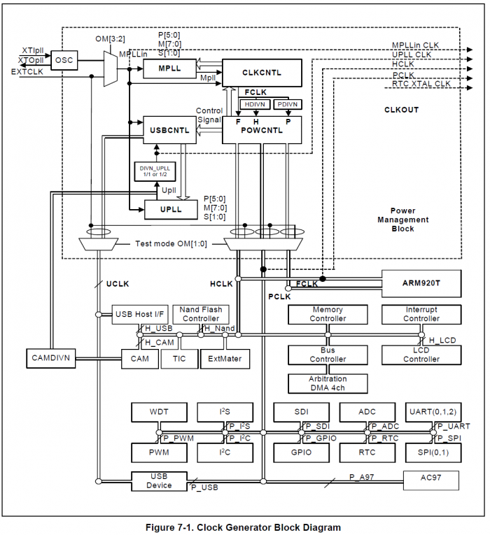
先来看看S3C2440时钟的硬件框图:
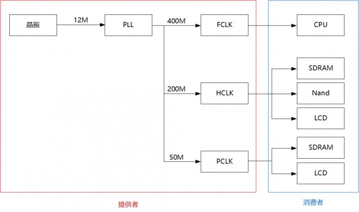
将该图简化如下:
我们只想作为消费者怎么去使用这些时钟,并不关心“提供者”内部的层级结构,只要知道“直接提供者”,也不关系“直接提供者”的实现,我们只需要发出请求就可以了。
晶振设备树描述
我们看看在2440的设备树里怎么描述这提供者和消费者。先来看看晶振:
	xti: xti_clock {
		compatible = "fixed-clock";
		clock-frequency = <12000000>;
		clock-output-names = "xti";
		#clock-cells = <0>;
	};
根据compatible可以找到对应的驱动,驱动程序将晶振的频率记录下来,以后作为计算的基准。
然后再是PLL的设备节点:
	clocks: clock-controller@4c000000 {
		compatible = "samsung,s3c2440-clock";
		reg = <0x4c000000 0x20>;
		#clock-cells = <1>;
	};
设备节点本身非常简单,复杂的是它对应的驱动程序。在驱动程序里面,肯定会根据reg获得寄存器的地址,然后设置各种内容。
大部分的芯片为了省电,它的外部模块时钟平时都是关闭的,只有在使用某个模块时,才设置相应的寄存器开启对应的时钟。
这些使用者各有不同,要怎么描述这些使用者呢?
我们可以为它们配上一个ID。在设备树中的#clock-cells = <1>;表示 用多少个u32位来描述消费者。在本例中使用一个u32来描述。
这些ID值由谁提供的?
是由驱动程序提供的,该节点会对应一个驱动程序,驱动程序给硬件(消费者)都分配了一个ID,所以说复杂的操作都留给驱动程序来做。
LCD时钟设备树描述
消费者想使用时钟时,首先要找到时钟的直接提供者,向它发出申请。以LCD为例:
    fb0: fb@4d000000{
        compatible = "jz2440,lcd";
        reg = <0x4D000000 0x60>;
        interrupts = <0 0 16 3>;
        clocks = <&clocks HCLK_LCD>;
        clock-names = "lcd";
        ……
	}
在clock属性里,首先要确定向谁发出时钟申请,这里是向clocks发出申请,然后确定想要时钟提供者提供哪一路时钟,这里是HCLK_LCD,在驱动程序里定义了该宏,每种宏对应了一个时钟ID。
定义如下:
……
/* hclk-gates */
#define HCLK_LCD		32
#define HCLK_USBH		33
#define HCLK_USBD		34
#define HCLK_NAND		35
#define HCLK_CAM		36
……
因此,我们只需要在设备节点定义clocks这个属性,这个属性确定时钟提供者,然后确定时钟ID,也就是向时钟提供者申请哪一路时钟。
对应的内核文档可以参考这两个文件:
Documentation/devicetree/bindings/clock/clock-bindings.txt
Documentation/devicetree/bindings/clock/samsung,s3c2410-clock.txt
那么我这个设备驱动程序,怎么去使用这些时钟呢?
以前的驱动程序:clk_get(NULL, "name"); clk_prepare_enable(clk);
现在的驱动程序:of_clk_get(node, 0); clk_prepare_enable(clk);
总结
a. 设备树中定义了各种时钟, 在文档中称之为"Clock providers", 比如:
	clocks: clock-controller@4c000000 {
		compatible = "samsung,s3c2440-clock";
		reg = <0x4c000000 0x20>;
		#clock-cells = <1>;      // 想使用这个clocks时要提供1个u32来指定它, 比如选择这个clocks中发出的LCD时钟、PWM时钟
	};
b. 设备需要时钟时, 它是"Clock consumers", 它描述了使用哪一个"Clock providers"中的哪一个时钟(id), 比如:
    fb0: fb@4d000000{
        compatible = "jz2440,lcd";
        reg = <0x4D000000 0x60>;
        interrupts = <0 0 16 3>;
        clocks = <&clocks HCLK_LCD>;  // 使用clocks即clock-controller@4c000000中的HCLK_LCD
	};
c. 驱动中获得/使能时钟:
	// 确定时钟个数
	int nr_pclks = of_count_phandle_with_args(dev->of_node, "clocks",
						"#clock-cells");
	// 获得时钟
	for (i = 0; i < nr_pclks; i++) {
		struct clk *clk = of_clk_get(dev->of_node, i);
	}

	// 使能时钟
	clk_prepare_enable(clk);

	// 禁止时钟
	clk_disable_unprepare(clk);
第03节_在设备树中pinctrl的简单使用
这节课讲解在设备树中pinctrl的简单使用,pinctrl从名字上就可以猜到它是控制引脚的。
基本概念
在讲解使用方法前,先讲解几个概念。
Bank: 以引脚名为依据, 这些引脚分为若干组, 每组称为一个Bank
- 比如s3c2440里有GPA、GPB、GPC等Bank,
- 每个Bank中有若干个引脚, 比如GPA0,GPA1, ..., GPC0, GPC1,...等引脚
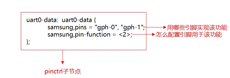
Group: 以功能为依据, 具有相同功能的引脚称为一个Group
- 比如s3c2440中串口0的TxD、RxD引脚使用 GPH2,GPH3, 那这2个引脚可以列为一组
- 比如s3c2440中串口0的流量控制引脚使用 GPH0,GPH1, 那这2个引脚也可以列为一组
State: 设备的某种状态, 比如内核自己定义的"default","init","idel","sleep"状态;
- 也可以是其他自己定义的状态, 比如串口的"flow_ctrl"状态(使用流量控制)
- 设备处于某种状态时, 它可以使用若干个Group引脚
当串口处于“default”状态时,它是由pinctrl-0指定若干组(group)引脚; 当串口处于“sleep”状态时,它是由pinctrl-1指定若干组(group)引脚;
设备的pinctrl的设置时机
a. platform_device, platform_driver匹配时:
"第3课第06节_platform_device跟platform_driver的匹配" 中讲解了platform_device和platform_driver的匹配过程,最终都会调用到 really_probe (drivers/base/dd.c)
really_probe:
	/* If using pinctrl, bind pins now before probing */
	ret = pinctrl_bind_pins(dev);
				dev->pi ns->default_state = pinctrl_lookup_state(dev->pins->p,
								PINCTRL_STATE_DEFAULT);  /* 获得"default"状态的pinctrl */
				dev->pins->init_state = pinctrl_lookup_state(dev->pins->p,
								PINCTRL_STATE_INIT);    /* 获得"init"状态的pinctrl */

				ret = pinctrl_select_state(dev->pins->p, dev->pins->init_state);    /* 优先设置"init"状态的引脚 */
				ret = pinctrl_select_state(dev->pins->p, dev->pins->default_state); /* 如果没有init状态, 则设置"default"状态的引脚 */

	......
	ret = drv->probe(dev);
所以: 如果设备节点中指定了pinctrl, 在对应的probe函数被调用之前, 先"bind pins", 即先绑定、设置引脚
b. 驱动中想选择、设置某个状态的引脚:
   devm_pinctrl_get_select_default(struct device *dev);      // 使用"default"状态的引脚
   pinctrl_get_select(struct device *dev, const char *name); // 根据name选择某种状态的引脚

   pinctrl_put(struct pinctrl *p);   // 不再使用, 退出时调用
第04节_使用设备树给LCD指定各种参数
参考文章: 讓TQ2440也用上設備樹(1) http://www.cnblogs.com/pengdonglin137/p/6241895.html
参考代码: https://github.com/pengdonglin137/linux-4.9/blob/tq2440_dt/drivers/video/fbdev/s3c2410fb.c
实验方法: 所用文件在: doc_and_sources_for_device_tree\source_and_images\第5,6课的源码及映像文件(使用了完全版的设备树)\第6课第4节_LCD驱动\02th_我修改的
a. 替换dts文件: 把"jz2440_irq.dts" 放入内核 arch/arm/boot/dts目录,
b. 替换驱动文件: 把"s3c2410fb.c" 放入内核 drivers/video/fbdev/ 目录, 修改 内核 drivers/video/fbdev/Makefile : obj-$(CONFIG_FB_S3C2410) += lcd_4.3.o 改为: obj-$(CONFIG_FB_S3C2410) += s3c2410fb.o
c. 编译驱动、编译dtbs: export PATH=PATH=/usr/local/sbin:/usr/local/bin:/usr/sbin:/usr/bin:/sbin:/bin:/usr/games:/work/system/gcc-linaro-4.9.4-2017.01-x86_64_arm-linux-gnueabi/bin cp config_ok .config make uImage // 生成 arch/arm/boot/uImage make dtbs // 生成 arch/arm/boot/dts/jz2440_irq.dtb
d. 使用上述uImage, dtb启动内核即可看到LCD有企鹅出现
(1). 设备树中的描述:
   fb0: fb@4d000000{
       compatible = "jz2440,lcd";
       reg = <0x4D000000 0x60>;
       interrupts = <0 0 16 3>;
       clocks = <&clocks HCLK_LCD>;   /* a. 时钟的处理 */
       clock-names = "lcd";
       pinctrl-names = "default";     /* b. pinctrl */
       pinctrl-0 = <&lcd_pinctrl &lcd_backlight &gpb0_backlight>;/*添加一组背光控制引脚*/
       status = "okay";
/* c. 根据LCD引脚特性设置lcdcon5, 指定lcd时序参数 */
       lcdcon5 = <0xb09>;
       type = <0x60>;
       width = /bits/ 16 <480>;
       height = /bits/ 16 <272>;
       pixclock = <100000>;       /* 单位: ps, 10^-12 S,  */
       xres = /bits/ 16 <480>;
       yres = /bits/ 16 <272>;
       bpp = /bits/ 16 <16>;
       left_margin = /bits/ 16 <2>;
       right_margin =/bits/ 16  <2>;
       hsync_len = /bits/ 16 <41>;
       upper_margin = /bits/ 16 <2>;
       lower_margin = /bits/ 16 <2>;
       vsync_len = /bits/ 16 <10>;
   };
&pinctrl_0 { gpb0_backlight: gpb0_backlight { samsung,pins = "gpb-0"; samsung,pin-function = <1>; samsung,pin-val = <1>; }; };
(2) 代码中的处理:
a. 时钟的处理:
info->clk = of_clk_get(dev->of_node, 0);
clk_prepare_enable(info->clk);
b. pinctrl:
代码中无需处理, 在 platform_device/platform_driver匹配之后就会设置"default"状态对应的pinctrl
配置gpio引脚为lcd功能,查看文件jz2440_irq_all.dts lcd_pinctrl { samsung,pins = "gpc-8", "gpc-9", "gpc-10", "gpc-11", "gpc-12", "gpc-13", "gpc-14", "gpc-15", "gpd-0", "gpd-1", "gpd-2", "gpd-3", "gpd-4", "gpd-5", "gpd-6", "gpd-7", "gpd-8", "gpd-9", "gpd-10", "gpd-11", "gpd-12", "gpd-13", "gpd-14", "gpd-15", "gpc-1", "gpc-2", "gpc-3", "gpc-4"; samsung,pin-function = <0x2>; phandle = <0x8>; }; 背光引脚,用来使能lcd电源 lcd_backlight { samsung,pins = "gpg-4"; samsung,pin-function = <0x3>; phandle = <0x9>; }; 背光引脚 gpb0_backlight { samsung,pins = "gpb-0"; samsung,pin-function = <0x1>;//引脚功能为输出 samsung,pin-val = <0x1>;//初始电平为1 phandle = <0xa>; }; c. 根据LCD引脚特性设置lcdcon5, 指定lcd时序参数: 打开wiki看新一期加强版lcd编程的介绍
引用lcd页面
Vclk 每一个clk,电子枪移动一个像素,我们需要设置lcd的时钟参数,通过LCD芯片手册的参数进行设置
时钟f=10M=10*10^6 = 10^7 周期t=1/f=10^-7 = 10^-7 * 10^12 * 10^-12 s = 10^5皮秒 也就是pixclock值的由来
tu1..................
lcdcon5 = <0xb09>;含义是指定了LCD信号的极性
可以查看老的lcd驱动里面有注释,这些值也是根据LCD极性来确定
代码中如何处理lcd设备树节点属性?
直接读设备树节点中的各种属性值, 用来设置驱动参数
of_property_read_u32(np, "lcdcon5", (u32 *)(&display->lcdcon5)); of_property_read_u32(np, "type", &display->type); of_property_read_u16(np, "width", &display->width); of_property_read_u16(np, "height", &display->height); of_property_read_u32(np, "pixclock", &display->pixclock); of_property_read_u16(np, "xres", &display->xres); of_property_read_u16(np, "yres", &display->yres); of_property_read_u16(np, "bpp", &display->bpp); of_property_read_u16(np, "left_margin", &display->left_margin); of_property_read_u16(np, "right_margin", &display->right_margin); of_property_read_u16(np, "hsync_len", &display->hsync_len); of_property_read_u16(np, "upper_margin", &display->upper_margin); of_property_read_u16(np, "lower_margin", &display->lower_margin); of_property_read_u16(np, "vsync_len", &display->vsync_len); 新老版本lcd驱动的对比请看视频


