“I2C device tree configuration”的版本间的差异
Zhouyuebiao(讨论 | 贡献) |
|||
| (未显示同一用户的11个中间版本) | |||
| 第1行: | 第1行: | ||
== Article purpose == | == Article purpose == | ||
| − | + | 本文介绍了如何配置“ I2C内部外围设备”<ref name="I2C internal peripheral"> [[I2C internal peripheral]] </ref> ''' when the peripheral is assigned to Linux<sup>®</sup> OS''',尤其是: | |
| − | * | + | * 如何配置STM32 I2C外设 |
| − | * | + | * 如何配置板上或硬件扩展上存在的STM32外部I2C器件。 |
| − | + | 使用'''设备树机制'''执行配置<ref> [[Device tree]]</ref>. | |
| − | + | 它由“STM32 I2C Linux<sup>®</sup>驱动程序”使用,该驱动程序在 [[I2C overview|I2C]]框架中注册相关信息。 | |
| − | + | 如果将外围设备分配给另一个执行上下文,请参阅 [[How to assign an internal peripheral to a runtime context]] 文章,以获取有关外围设备分配和配置的准则。 | |
== DT bindings documentation == | == DT bindings documentation == | ||
| − | + | I2C表示为: | |
| − | * | + | * “I2C总线的通用设备树绑定”<ref name="i2c.txt">{{CodeSource | Linux kernel | Documentation/devicetree/bindings/i2c/i2c.txt}}, Generic device tree bindings for I2C busses</ref> |
| − | * | + | *“STM32 I2C控制器设备树绑定”<ref name="i2c-stm32.txt ">{{CodeSource |Linux kernel | Documentation/devicetree/bindings/i2c/i2c-stm32.txt}}</ref> |
== DT configuration == | == DT configuration == | ||
| − | + | 该硬件描述是'''STM32微处理器'''设备树文件(扩展名为.dtsi)和'''板子'''设备树文件(扩展名为.dts)的组合。 有关设备树文件分割的说明,请参见[[Device tree]]。 | |
| − | '''STM32CubeMX''' | + | '''STM32CubeMX'''可用于生成板卡设备树。有关更多详细信息,请参考[[#How_to_configure_the_DT_using_STM32CubeMX|How to configure the DT using STM32CubeMX]]。 |
===DT configuration (STM32 level) === | ===DT configuration (STM32 level) === | ||
| − | + | 在设备级,I2C控制器声明如下: | |
<pre> | <pre> | ||
i2c2: i2c@40013000 { | i2c2: i2c@40013000 { | ||
| 第43行: | 第43行: | ||
}; | }; | ||
</pre> | </pre> | ||
| − | {{Warning| | + | {{Warning|该设备树部分与STM32微处理器有关。 它必须保持原样,而不能由最终用户修改。}} |
| − | + | 请参考DTS文件: stm32mp157c.dtsi<ref name=DTS>{{CodeSource | Linux kernel | arch/arm/boot/dts/stm32mp157c.dtsi}}</ref> | |
=== DT configuration (board level) === | === DT configuration (board level) === | ||
| 第67行: | 第67行: | ||
</pre> | </pre> | ||
| − | + | 设备树配置分为两个级别: | |
==== I²C internal peripheral related properties ==== | ==== I²C internal peripheral related properties ==== | ||
| − | + | 与I2C内部外围设备和I2C节点所属的I²C总线相关的设备树属性 | |
| − | * '''{{highlight|pinctrl-0&1}}''' | + | * '''{{highlight|pinctrl-0&1}}''' 配置取决于硬件板配置以及I2C设备如何连接到SCL,SDA(如果设备符合SMBus标准,则连接到SMBA)引脚。<br/> 有关引脚配置的更多详细信息,请参见: [[Pinctrl device tree configuration]] |
| − | * '''{{highlight|clock-frequency}}''' | + | * '''{{highlight|clock-frequency}}'''代表I2C总线速度:'''正常(100KHz)''','''快速(400KHz)'''和'''快速+(最高 1MHz)'''。该值以Hz为单位。 |
| − | * '''{{highlight|dmas}}''' | + | * '''{{highlight|dmas}}''' 默认情况下,所有I2C实例均启用DMA。如果不需要,则由用户决定是否“删除”。 |
| − | * '''{{highlight|i2c-scl-rising/falling-time-ns}}''' | + | ''{{highlight|/delete-property/}}'' 用于删除I2C的DMA使用情况。要删除DMA,必须同时插入'''{{highlight|/delete-property/dma-names}}''' 和 '''{{highlight|/delete-property/dmas}}'''。 |
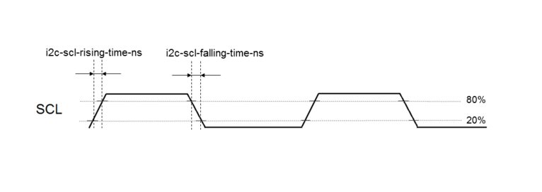
| − | {{Info| | + | * '''{{highlight|i2c-scl-rising/falling-time-ns}}'''是可选值,具体取决于板的硬件特性: 导线长度,电阻和电容的硬件设计。<br/> 这些值必须以纳秒为单位提供,并且可以通过观察示波器上的SCL上升和下降斜率来测量。请参见[[I2C device tree configuration#How to measure I2C timings | how to measure I2C timings]].<br/>I2C驱动程序使用此信息根据请求的 ''{{highlight|clock-frequency}}''来计算准确的I2C时序。 <br/>STM32CubeMX实现了遵循I2C标准并考虑用户输入的算法。 <br/>如果未提供这些值,则驱动程序将使用其默认值。 <br/>提供错误的参数将产生不正确的 ''{{highlight|clock-frequency}}''. 如果驱动程序未能根据用户输入计算时序参数(SCL上升/下降和时钟频率),则时钟频率将降级为较低的频率。'''示例''':如果用户将400 kHz指定为时钟频率,但是算法无法为指定的SCL上升和下降时间生成时序,则时钟频率将降至100 kHz。 |
| + | {{Info| 对于高于100KHz的I2C总线频率,强烈建议使用I2C时序。}} | ||
| − | + | ||
| − | * '''{{highlight|st,smbus-alert}}''' | + | * '''{{highlight|st,smbus-alert}}''' 可选属性允许启用驱动程序对SMBus Alert机制的处理。 启用后,只要从设备生成SMBus警报消息,就会调用从驱动程序的警报功能。 |
| − | * '''{{highlight|st,smbus-host-notify}}''' | + | * '''{{highlight|st,smbus-host-notify}}''' 可选属性允许启用驱动程序对SMBus Host Notify机制的处理。 启用后,每当从设备发送主机通知消息时,就会调用IRQ处理程序。 |
| − | {{Info| | + | {{Info| 请参阅Linux smbus-protocol文档 <ref name="smbus-protocol ">{{CodeSource |Linux kernel | Documentation/i2c/smbus-protocol}}</ref>了解有关SMBus警报和主机通知处理的更多详细信息。}} |
==== I²C devices related properties ==== | ==== I²C devices related properties ==== | ||
| − | + | 与连接到指定I²C总线的I²C设备有关的设备树属性。 每个I²C设备均由一个子节点表示。 | |
| − | * '''{{highlight|reg}}''' | + | |
| + | * '''{{highlight|reg}}''' 代表总线上的I2C外设从机地址。<br/> 请注意,某些从地址位对于框架可能具有特殊含义。 例如,31<sup>st</sup> 位表示10位设备功能。<br/> 有关更多详细信息,请参考i2c.txt <ref name="i2c.txt"/>。 | ||
====How to measure I2C timings==== | ====How to measure I2C timings==== | ||
| 第107行: | 第109行: | ||
}; | }; | ||
</pre> | </pre> | ||
| − | + | 上面的示例在地址0x50的i2c-X总线(X取决于运行时探测的适配器数量)上注册一个EEPROM设备,并且该实例与使用相同Compatible属性注册的驱动程序兼容。<br/> | |
| − | + | 请注意,驱动程序将使用MDMA进行数据传输,SCL上升/下降时间已作为输入提供。<br/> | |
====Example of an EEPROM slave device emulator registering on STM32 side==== | ====Example of an EEPROM slave device emulator registering on STM32 side==== | ||
| 第120行: | 第122行: | ||
}; | }; | ||
</pre> | </pre> | ||
| − | + | 上例在STM32侧的从机地址0x64处注册了一个EEPROM仿真器。 <br/> | |
| − | + | STM32充当I2C EEPROM,可通过连接在I2C总线上的外部主设备进行访问。 | |
====Example of a stts751 thermal sensor with SMBus Alert feature enabled==== | ====Example of a stts751 thermal sensor with SMBus Alert feature enabled==== | ||
| − | + | ||
| − | + | 当达到配置阈值时,stts751热传感器 <ref>https://www.st.com/en/mems-and-sensors/stts751.html</ref> 能够发送SMBus警报。</br> | |
| − | + | 可以在内核中启用设备驱动程序:</br> | |
[x] Device Drivers | [x] Device Drivers | ||
[x] Hardware Monitoring support | [x] Hardware Monitoring support | ||
[x] ST Microelectronics STTS751 | [x] ST Microelectronics STTS751 | ||
| − | + | 这可以在您的内核中手动完成: | |
CONFIG_SENSORS_STTS751=y | CONFIG_SENSORS_STTS751=y | ||
| − | + | 由于SMBus警报依靠专用引脚来工作,因此必须更新I2C控制器(此处为i2c2)的pinctrl以添加相应的SMBA引脚。</br> | |
| − | + | 对于i2c2控制器: | |
<pre> | <pre> | ||
i2c2_pins_a: i2c2-0 { | i2c2_pins_a: i2c2-0 { | ||
| 第159行: | 第161行: | ||
</pre> | </pre> | ||
| − | + | 在设备树中,必须添加st,smbus-alert属性以及启用stts751的节点。</br> | |
<pre> | <pre> | ||
| 第173行: | 第175行: | ||
==How to configure the DT using STM32CubeMX== | ==How to configure the DT using STM32CubeMX== | ||
| − | The [[STM32CubeMX]] | + | The [[STM32CubeMX]]工具可用于配置STM32MPU设备并获取相应的 [[Device_tree#STM32|platform configuration device tree]] 文件。<br /> |
| − | + | STM32CubeMX可能不支持以上[[#DT bindings documentation|DT bindings documentation]]段中描述的所有属性。 如果是这样,该工具会在生成的设备树中插入'''用户部分''' 。 然后可以编辑这些部分以添加一些属性,并将它们一代一代地保留下来。 有关更多信息,请参见[[STM32CubeMX]] 用户手册。 | |
==References== | ==References== | ||
| − | + | 请参考以下链接以获取更多信息: | |
<references /> | <references /> | ||
| − | |||
| − | |||
| − | |||
| − | |||
| − | |||
| − | |||
| − | |||
2020年11月8日 (日) 14:39的最新版本
目录
Article purpose
本文介绍了如何配置“ I2C内部外围设备”[1] when the peripheral is assigned to Linux® OS,尤其是:
- 如何配置STM32 I2C外设
- 如何配置板上或硬件扩展上存在的STM32外部I2C器件。
使用设备树机制执行配置[2].
它由“STM32 I2C Linux®驱动程序”使用,该驱动程序在 I2C框架中注册相关信息。
如果将外围设备分配给另一个执行上下文,请参阅 How to assign an internal peripheral to a runtime context 文章,以获取有关外围设备分配和配置的准则。
DT configuration
该硬件描述是STM32微处理器设备树文件(扩展名为.dtsi)和板子设备树文件(扩展名为.dts)的组合。 有关设备树文件分割的说明,请参见Device tree。
STM32CubeMX可用于生成板卡设备树。有关更多详细信息,请参考How to configure the DT using STM32CubeMX。
DT configuration (STM32 level)
在设备级,I2C控制器声明如下:
i2c2: i2c@40013000 {
	compatible = "st,stm32f7-i2c";
	reg = <0x5c002000 0x400>;
	interrupt-names = "event", "error", "wakeup";
	interrupts-extended = <&intc GIC_SPI 33 IRQ_TYPE_LEVEL_HIGH>,
			      <&intc GIC_SPI 34 IRQ_TYPE_LEVEL_HIGH>,
			      <&exti 22 1>;
	clocks = <&rcc I2C2_K>;
	resets = <&rcc I2C2_R>;
	#address-cells = <1>;
	#size-cells = <0>;
	dmas = <&dmamux1 35 0x400 0x05>,
	       <&dmamux1 36 0x400 0x05>;
	power-domains = <&pd_core>;
	st,syscfg-fmp = <&syscfg 0x4 0x2>;
	st,syscfg-fmp-clr = <&syscfg 0x44 0x2>;
	status = "disabled";
};
| 该设备树部分与STM32微处理器有关。 它必须保持原样,而不能由最终用户修改。 |
请参考DTS文件: stm32mp157c.dtsi[5]
DT configuration (board level)
&i2c3 {
	pinctrl-names = "default", "sleep";
	pinctrl-0 = <&i2c2_pins_a>;
	pinctrl-1 = <&i2c2_pins_sleep_a>;
	i2c-scl-rising-time-ns = <185>;
	i2c-scl-falling-time-ns = <20>;
        st,smbus-alert;
        st,smbus-host-notify;
	status = "okay";
	/delete-property/dmas;
	/delete-property/dma-names;

	ov5640: camera@3c {
         [...]
	};
};
设备树配置分为两个级别:
与I2C内部外围设备和I2C节点所属的I²C总线相关的设备树属性
-
pinctrl-0&1 配置取决于硬件板配置以及I2C设备如何连接到SCL,SDA(如果设备符合SMBus标准,则连接到SMBA)引脚。
有关引脚配置的更多详细信息,请参见: Pinctrl device tree configuration - clock-frequency代表I2C总线速度:正常(100KHz),快速(400KHz)和快速+(最高 1MHz)。该值以Hz为单位。
- dmas 默认情况下,所有I2C实例均启用DMA。如果不需要,则由用户决定是否“删除”。
/delete-property/ 用于删除I2C的DMA使用情况。要删除DMA,必须同时插入/delete-property/dma-names 和 /delete-property/dmas。
-
i2c-scl-rising/falling-time-ns是可选值,具体取决于板的硬件特性: 导线长度,电阻和电容的硬件设计。
这些值必须以纳秒为单位提供,并且可以通过观察示波器上的SCL上升和下降斜率来测量。请参见 how to measure I2C timings.
I2C驱动程序使用此信息根据请求的 clock-frequency来计算准确的I2C时序。
STM32CubeMX实现了遵循I2C标准并考虑用户输入的算法。
如果未提供这些值,则驱动程序将使用其默认值。
提供错误的参数将产生不正确的 clock-frequency. 如果驱动程序未能根据用户输入计算时序参数(SCL上升/下降和时钟频率),则时钟频率将降级为较低的频率。示例:如果用户将400 kHz指定为时钟频率,但是算法无法为指定的SCL上升和下降时间生成时序,则时钟频率将降至100 kHz。
| 对于高于100KHz的I2C总线频率,强烈建议使用I2C时序。 |
- st,smbus-alert 可选属性允许启用驱动程序对SMBus Alert机制的处理。 启用后,只要从设备生成SMBus警报消息,就会调用从驱动程序的警报功能。
- st,smbus-host-notify 可选属性允许启用驱动程序对SMBus Host Notify机制的处理。 启用后,每当从设备发送主机通知消息时,就会调用IRQ处理程序。
| 请参阅Linux smbus-protocol文档 [6]了解有关SMBus警报和主机通知处理的更多详细信息。 |
与连接到指定I²C总线的I²C设备有关的设备树属性。 每个I²C设备均由一个子节点表示。
-
reg 代表总线上的I2C外设从机地址。
请注意,某些从地址位对于框架可能具有特殊含义。 例如,31st 位表示10位设备功能。
有关更多详细信息,请参考i2c.txt [3]。
DT configuration examples
Example of an external EEPROM slave device
i2c4: {
    status = "okay";
    i2c-scl-rising-time-ns = <185>;
    i2c-scl-falling-time-ns = <20>;

    eeprom@50 {
        compatible = "at,24c256";
        pagesize = <64>;
        reg = <0x50>;
    };
};
上面的示例在地址0x50的i2c-X总线(X取决于运行时探测的适配器数量)上注册一个EEPROM设备,并且该实例与使用相同Compatible属性注册的驱动程序兼容。
请注意,驱动程序将使用MDMA进行数据传输,SCL上升/下降时间已作为输入提供。
Example of an EEPROM slave device emulator registering on STM32 side
i2c4: {
    eeprom@64 {
        status = "okay";
        compatible = "linux,slave-24c02";
        reg = <0x40000064>;
    };
};
上例在STM32侧的从机地址0x64处注册了一个EEPROM仿真器。
STM32充当I2C EEPROM,可通过连接在I2C总线上的外部主设备进行访问。
Example of a stts751 thermal sensor with SMBus Alert feature enabled
当达到配置阈值时,stts751热传感器 [7] 能够发送SMBus警报。
可以在内核中启用设备驱动程序:
[x] Device Drivers
    [x] Hardware Monitoring support
        [x] ST Microelectronics STTS751
这可以在您的内核中手动完成:
CONFIG_SENSORS_STTS751=y
由于SMBus警报依靠专用引脚来工作,因此必须更新I2C控制器(此处为i2c2)的pinctrl以添加相应的SMBA引脚。
对于i2c2控制器:
i2c2_pins_a: i2c2-0 {
    pins {
        pinmux = <STM32_PINMUX('H', 4, AF4)>, /* I2C2_SCL */
                        <STM32_PINMUX('H', 5, AF4)>, /* I2C2_SDA */
                        <STM32_PINMUX('H', 6, AF4)>; /* I2C2_SMBA */
        bias-disable;
        drive-open-drain;
        slew-rate = <0>;
    };
};

i2c2_pins_sleep_a: i2c2-1 {
    pins {
        pinmux = <STM32_PINMUX('H', 4, ANALOG)>, /* I2C2_SCL */
                        <STM32_PINMUX('H', 5, ANALOG)>, /* I2C2_SDA */
                        <STM32_PINMUX('H', 6, ANALOG)>; /* I2C2_SMBA */
    };
};
在设备树中,必须添加st,smbus-alert属性以及启用stts751的节点。
i2c2: {
    st,smbus-alert;
    stts751@3b {
        status = "okay";
        compatible = "stts751";
        reg = <0x3b>;
    };
};
How to configure the DT using STM32CubeMX
The STM32CubeMX工具可用于配置STM32MPU设备并获取相应的 platform configuration device tree 文件。
STM32CubeMX可能不支持以上DT bindings documentation段中描述的所有属性。 如果是这样,该工具会在生成的设备树中插入用户部分 。 然后可以编辑这些部分以添加一些属性,并将它们一代一代地保留下来。 有关更多信息,请参见STM32CubeMX 用户手册。
References
请参考以下链接以获取更多信息:
- ↑ I2C internal peripheral
- ↑ Device tree
- ↑ 3.03.1 Documentation/devicetree/bindings/i2c/i2c.txt| |}} Documentation/devicetree/bindings/i2c/i2c.txt , Generic device tree bindings for I2C busses
- ↑ Documentation/devicetree/bindings/i2c/i2c-stm32.txt| |}} Documentation/devicetree/bindings/i2c/i2c-stm32.txt
- ↑ arch/arm/boot/dts/stm32mp157c.dtsi| |}} arch/arm/boot/dts/stm32mp157c.dtsi
- ↑ Documentation/i2c/smbus-protocol| |}} Documentation/i2c/smbus-protocol
- ↑ https://www.st.com/en/mems-and-sensors/stts751.html